
Capacitors And Capacitance are becoming strategic purchasing considerations as electronics become smaller, faster, and more power-conscious. Grand View Research identifies continued growth in the global capacitor market, supported by electric vehicles, renewable-energy systems, industrial automation, and consumer electronics. Fortune Business Insights also highlights increasing demand for multilayer ceramic capacitors, aluminum electrolytic capacitors, and film capacitors across power and control applications. These trends matter to buyers because component selection affects reliability, heat management, filtering performance, and total ownership cost.
The market is not simple.
A ceramic capacitor may fit a smartphone power rail, while a film capacitor may better serve an inverter DC link. Aluminum electrolytics still offer useful capacitance density, especially in power supplies, but their lifetime can change sharply with temperature and ripple current. Tantalum and polymer capacitors may provide stable performance in compact circuits, yet their voltage derating and failure behavior require careful review. Yole Group’s electronics research repeatedly points to automotive electrification and power semiconductor growth as major drivers for advanced passive components. Buyers should connect these forecasts with actual datasheet evidence, not marketing claims.
This 2026 guide compares major capacitor and capacitance types through practical purchasing criteria. It examines rated voltage, tolerance, equivalent series resistance, ripple current, leakage current, temperature range, aging, package size, and supply continuity. IEC 60384 standards and AEC-Q200 qualification provide useful reference points for reliability evaluation. Still, no universal winner exists. A capacitor selected only by price can create hidden redesign costs, and even reputable reports cannot replace circuit-level testing. Wise procurement combines supplier history, validated samples, lifecycle data, and application experience. That approach is less dramatic, but usually more dependable.
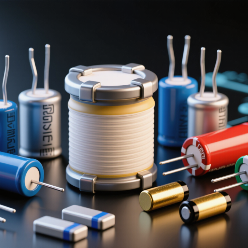
For buyers, capacitance begins with charge storage. One farad stores one coulomb at one volt. The practical equation is C = εA/d. Higher dielectric permittivity, larger electrode area, or thinner spacing increases capacitance. Each choice affects voltage strength, heat, and reliability.
DC bias can quietly reduce a ceramic capacitor’s usable value. A part marked 10 µF may deliver far less at its rated voltage. Check the capacitance curve at the actual operating bias and temperature. A 5 V rail, 3.3 V rail, and 48 V bus require different verification habits. Tolerance alone is not enough. This is where many purchasing decisions become too optimistic.
Application demand is rising. The International Energy Agency’s Global EV Outlook 2025 reports more than 17 million electric cars were sold in 2024, increasing demand for compact power electronics. The U.S. Department of Energy’s Energy Storage Grand Challenge Roadmap also emphasizes higher efficiency, safety, and lifecycle performance in energy systems. Buyers should compare ripple current, ESR, leakage, aging, and derating data, not only farads per dollar. Measurements can disagree with the datasheet. That possibility deserves attention.
In 2026, capacitor selection depends on more than capacitance and voltage ratings. Buyers should examine ripple current, temperature, lifetime, leakage, tolerance, and mounting space. The four core families behave differently under real operating conditions.
MLCCs offer compact size, low equivalent series resistance, and excellent high-frequency performance. They suit decoupling near processors and switching devices. However, capacitance can fall sharply under DC bias. Mechanical cracking is another concern, especially on rigid circuit boards.
Aluminum electrolytic capacitors provide high capacitance at a moderate cost. They work well in power smoothing and bulk energy storage. Their electrolyte can dry over time, particularly near heat sources. Ripple current and rated lifetime deserve careful review.
Tantalum capacitors provide stable capacitance in compact packages, making them useful where board space is limited. They require disciplined voltage derating and controlled surge conditions. A small design shortcut can create a serious reliability problem.
Film capacitors deliver low loss, strong pulse handling, and excellent long-term stability. They are valuable in filters, motor circuits, and power conversion systems, though their larger size may complicate layouts.
Do not compare families by price alone. Check impedance across frequency, inspect derating curves, and request traceable test data. A datasheet may appear reassuring, yet actual thermal conditions can expose weaknesses. Prototype testing remains necessary, and even experienced teams sometimes select a technically correct capacitor that fits poorly in the final assembly.
When selecting MLCCs in 2026, buyers should separate temperature stability from capacitance density. C0G/NP0 capacitors typically hold capacitance within about ±30 ppm/°C across their rated temperature range. That equals a small drift, even near sensitive timing circuits. A 10 nF part may change only slightly from room temperature to a warmer enclosure. This behavior suits oscillators, filters, sensors, and precision measurement equipment.
X7R capacitors are specified differently. Their capacitance can vary by approximately ±15% across the declared temperature range. That figure is much larger, but X7R parts offer higher capacitance in smaller packages. They often support power decoupling, control electronics, and compact embedded assemblies. The comparison is not perfectly equal. One specification uses ppm per degree, while the other uses percentage change. Buyers should check the full temperature curve instead of comparing symbols alone.
Real testing still matters. Apply the intended DC voltage, because ceramic capacitance can fall under bias. Check aging, package size, tolerance, and ripple conditions. A device marked 100 nF may deliver less effective capacitance at operating voltage. I have seen designs pass room-temperature checks, then drift during thermal cycling. That mistake is easy to repeat. It is also worth reviewing supplier test methods and production consistency. C0G can be unnecessarily expensive for ordinary bypassing, while X7R may be too unstable for a precision reference. The better choice depends on the circuit’s actual temperature and voltage exposure.
| Capacitor Type | Dielectric or Construction | Operating Temperature | Capacitance Stability | Typical Tolerance | Typical Capacitance Range | Common Voltage Range | Polarity | ESR and Frequency Behavior | Typical Buyer Applications |
|---|---|---|---|---|---|---|---|---|---|
| C0G / NP0 MLCC Class 1 ceramic | Non-ferroelectric ceramic dielectric with very low temperature dependence. | -55°C to +125°C or higher, depending on the component specification. | ±30 ppm/°C is the common C0G/NP0 temperature coefficient limit. | ±0.1%, ±0.25%, ±0.5%, ±1%, ±2%, or ±5% are common options. | Approximately 0.5 pF to 100 nF; higher values may be available in larger case sizes. | Typically 16 V to 3 kV, with high-voltage versions available. | Non-polarized. | Very low ESR and low loss; capacitance is highly stable with applied DC voltage and frequency. | Precision timing, RF filters, resonant circuits, oscillators, sensors, precision analog, and high-stability signal paths. |
| X7R MLCC Class 2 ceramic | High-permittivity ceramic dielectric designed for compact, general-purpose energy storage and bypassing. | -55°C to +125°C. | ±15% maximum capacitance change over the rated temperature range. | ±1%, ±5%, ±10%, and ±20% are common options. | Approximately 10 pF to 100 µF, depending on case size, voltage rating, and construction. | Typically 6.3 V to 3 kV. | Low ESR and low ESL; capacitance can decrease under DC bias, especially in small, high-value parts. | Power-rail decoupling, digital electronics, industrial controls, automotive electronics, filtering, and general-purpose bypassing. | |
| X5R MLCC Class 2 ceramic | High-permittivity ceramic optimized for high capacitance in a small package. | -55°C to +85°C. | ±15% maximum capacitance change over the specified temperature range. | ±5%, ±10%, and ±20% are common options. | Approximately 100 pF to 100 µF or more, depending on size and voltage. | Typically 4 V to 100 V. | Low ESR and ESL; significant DC-bias derating should be included in the design calculation. | Compact consumer electronics, portable equipment, digital power rails, battery-powered devices, and signal bypassing. | |
| Y5V MLCC Class 2 ceramic | Very high-permittivity ceramic offering high nominal capacitance at low cost and small size. | -30°C to +85°C. | Capacitance change can be approximately +22% to -82% across the rated temperature range. | Commonly ±20%; tighter tolerances are less typical. | Approximately 1 nF to 1 µF or more, depending on construction. | Typically 6.3 V to 50 V. | Low ESR, but capacitance may fall substantially with DC bias, temperature, aging, and applied voltage. | Non-critical bypassing, low-cost consumer circuits, and applications where capacitance variation is acceptable. | |
| Plastic Film Capacitor Polyester, polypropylene, or related film | Metalized or foil electrodes separated by a polymer film dielectric. | Commonly -55°C to +85°C or +105°C; some constructions reach +125°C or higher. | Typically better than electrolytic types; polypropylene provides especially low loss and strong stability. | Commonly ±1%, ±2%, ±5%, or ±10%. | Approximately 1 nF to 100 µF, with larger values available in power-film constructions. | Typically 50 V to several kV. | Low dissipation factor and strong pulse capability; size increases rapidly at high capacitance and voltage. | AC filtering, snubbers, motor drives, power conversion, timing, audio, pulse circuits, and safety-rated suppression. | |
| Aluminum Electrolytic Capacitor Wet electrolytic | Aluminum oxide dielectric with a liquid electrolyte and high surface-area anode foil. | Common ratings include -40°C to +85°C, +105°C, or +125°C. | Capacitance changes with temperature, frequency, aging, and applied voltage; leakage current is comparatively higher. | Commonly -20% to +20%; other tolerances are available. | Approximately 1 µF to 100,000 µF. | Typically 6.3 V to 630 V. | Polarized; reverse voltage can cause damage. | Moderate to high ESR compared with ceramic and film types; ripple-current and lifetime ratings are important. | Bulk DC-link filtering, power supplies, motor controls, industrial equipment, and energy smoothing. |
| Aluminum Polymer Capacitor Solid conductive polymer | Aluminum oxide dielectric with a solid conductive polymer electrolyte. | Commonly -55°C to +105°C or +125°C. | Generally more stable and lower impedance than wet aluminum electrolytics, but still affected by temperature and bias. | Commonly ±20%. | Approximately 10 µF to 3,300 µF. | Typically 2.5 V to 100 V. | Usually polarized. | Low ESR, high ripple-current capability, and good transient response; voltage derating is recommended. | CPU and processor power rails, compact DC-DC converters, high-ripple power supplies, and low-voltage digital systems. |
| Tantalum Capacitor Solid tantalum, MnO2 or polymer | Tantalum oxide dielectric with manganese dioxide or conductive polymer cathode systems. | Commonly -55°C to +125°C. | Better volumetric efficiency than many aluminum electrolytics; capacitance varies with temperature, frequency, and DC bias. | Commonly ±10% or ±20%. | Approximately 0.1 µF to 2,200 µF. | Typically 2.5 V to 125 V, depending on construction. | Polarized; voltage derating is strongly recommended. | Low to moderate ESR; polymer versions generally provide lower ESR and better ripple performance than MnO2 versions. | Stable bulk decoupling, portable electronics, telecommunications, instrumentation, and space-constrained power rails. |
| Mica Capacitor Natural or synthetic mica | Mica dielectric with metal electrodes, selected for low loss and high stability. | Commonly -55°C to +125°C or +150°C. | Very low temperature coefficient, low aging, and strong voltage stability. | Commonly ±1%, ±2%, or ±5%. | Approximately 1 pF to 10 nF. | Typically 100 V to 2.5 kV. | Non-polarized. | Very low loss and excellent high-frequency performance; generally larger and more expensive than ceramic alternatives. | RF resonant circuits, high-voltage tuning, precision filters, transmitters, and high-stability instrumentation. |
| Electric Double-Layer Capacitor Supercapacitor | Electrochemical charge storage using porous electrodes and an electrolyte rather than a conventional dielectric. | Commonly -40°C to +65°C or +85°C. | Very high capacitance, but substantial voltage dependence, leakage current, self-discharge, and aging effects. | Approximately 0.1 F to 3,000 F per cell or module. | Typically 2.3 V to 3.0 V per cell; modules use series-connected cells for higher voltage. | Polarity must be observed. | Low energy-loss behavior for short-duration storage, but ESR is much higher than that of small ceramic capacitors. | Memory backup, regenerative braking, peak-power support, energy harvesting, industrial ride-through, and short-term power buffering. | |
| Buyer note: Values shown are typical industry ranges rather than guaranteed specifications. Confirm capacitance at the actual operating voltage, frequency, temperature, ripple current, lifetime, and mounting conditions using the selected component datasheet. | |||||||||
Choosing capacitors in 2026 requires more than comparing capacitance and voltage. In real power supplies, ESR creates heat when ripple current flows. A low ESR value can reduce losses, but it may also affect control-loop stability. Check the ESR curve across frequency and temperature, not only the headline value. ESL matters during fast switching. A short, wide current path usually performs better than a long lead.
Ripple current ratings need careful interpretation. Some datasheets specify RMS current at 100 kHz and 105°C, while your circuit may operate at a different frequency. Recalculate the expected heating. Then leave practical margin. A capacitor sitting beside a hot inductor may experience far more stress than the board average suggests. I have seen acceptable laboratory results fail after enclosure temperatures rose.
Leakage current is also important in battery devices, sensors, and backup circuits. It can increase with voltage, temperature, and aging. Measure it after the specified stabilization time. Immediate readings can mislead.
For 105–125°C applications, confirm the rated life, test temperature, ripple conditions, and voltage derating. A common rule estimates that life doubles for each 10°C reduction, but this is not universal. Treat it as a guide, not proof. Mechanical vibration, humidity, and repeated thermal cycling can shorten life beyond the datasheet model. Request test conditions, lot traceability, and independent verification before approving a large purchase.
For 2026 capacitor buying, a clear selection matrix reduces costly redesigns. I compare voltage margin, tolerance, case size, and IEC 60384 requirements together. When I review a capacitor list, I start with the highest continuous operating voltage. Do not match voltage exactly. A practical margin should cover ripple, temperature, surges, and supply variation. The required margin depends on the circuit, dielectric, and safety assessment. Excessive voltage rating can increase size and cost, so bigger is not automatically safer.
Tolerance affects timing, filtering, energy storage, and control-loop behavior. A 5% part may suit a general bypass position, while precision networks may need tighter limits. I also check capacitance drift across temperature and aging. Case size matters beyond the circuit board footprint. A compact case can restrict ripple-current cooling, spacing, and mechanical stability. Measure the real mounting area, including terminals and inspection clearance. I have seen designs pass schematic review but fail during assembly.
For IEC 60384, identify the applicable part specification and test conditions, rather than citing the series broadly. Review rated voltage, endurance, climatic category, insulation, and marking requirements. Request traceable test records and current datasheets from qualified suppliers. My matrix usually includes a risk column for surge exposure, heat, and supply continuity. It is not perfect. Early estimates often miss installation temperature or actual ripple waveforms. Recheck those assumptions before approving the purchase.
