
What Are the Top PCB Terminal Block Types in 2026?

A Pcb Terminal Block can look like a small green component on a crowded board. Yet its pitch, clamping method, and current rating affect wiring access, assembly time, and long-term reliability. In 2026, engineers will still weigh familiar choices: screw, spring-clamp, push-in, pluggable, and barrier-style designs. The right option depends on the application—not on a trend alone.

Market context helps, but it needs careful interpretation. Grand View Research’s Terminal Blocks Market report estimated the global market at USD 4.13 billion in 2023 and projected a 5.7% compound annual growth rate through 2030. That figure covers terminal blocks broadly; it is not a PCB-only forecast. Quality expert W. Edwards Deming is widely associated with the principle, “Quality is everyone’s responsibility.” Applied here, that means checking the whole connection: wire size, board layout, temperature rise, vibration, and access for maintenance. Small details matter.

This guide compares the leading PCB terminal block types by connection method, installation needs, and practical trade-offs. It also flags details that product tables can hide, such as tool access beside a neighboring enclosure or whether a plug can be removed without disturbing adjacent wiring. Those checks are not glamorous. They can prevent avoidable redesigns. Use the comparisons as a starting point, then confirm ratings and suitability against the manufacturer’s current datasheet and the actual operating conditions.
What Are the Top PCB Terminal Block Types in 2026?

What PCB Terminal Blocks Are and How They Mount

What Are the Top PCB Terminal Block Types in 2026?

What PCB Terminal Blocks Are and How They Mount

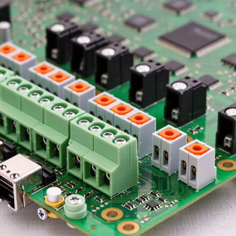
A PCB terminal block connects external wires to a printed circuit board. Inside, a screw or spring clamp holds each conductor against a metal contact. This creates a removable connection for power or signals. You can find them in control panels, sensors, and compact equipment. Their pitch, current rating, and wire capacity must suit the board and application.

Most PCB terminal blocks mount through holes in the board. Metal pins pass through drilled holes and are soldered to copper pads, creating a firm mechanical and electrical joint. Some designs use surface-mount soldering, while plug-in types pair a fixed board header with a removable connector. During assembly, align the pins carefully and check the specified soldering method. A block that looks straight can still sit unevenly. Keep it square. That small detail matters when wires are later inserted or removed.

Which Design Factors Distinguish PCB Terminal Block Types

What Are the Top PCB Terminal Block Types in 2026?

Which Design Factors Distinguish PCB Terminal Block Types

Screw-clamp blocks allow firm wire tightening, but need tool access and periodic torque checks. Spring-clamp and push-in types speed assembly and resist loosening under vibration. Pluggable blocks make servicing easier; however, their mating headers add height and another connection point. Through-hole versions suit many power designs, while surface-mount types can support automated assembly. Grand View Research’s 2024 Terminal Block Market report estimated the wider global market at about US$4.2 billion in 2023, with projected growth of 5.7% annually through 2030. This includes more than PCB-mounted products, so it is useful context, not a PCB-specific forecast.

Type selection depends on rated current, voltage, wire size, pitch, orientation, and expected temperature rise. Check the terminal’s datasheet and the PCB’s copper capacity together; a generous terminal rating does not guarantee a cool board. Creepage and clearance distances matter, too, especially where voltage is high. Vibration, enclosure space, wiring direction, and rework access also shape the choice. A tidy CAD fit can still be awkward to wire in a real enclosure. Pitch alone is a poor shortcut.

Tips: Prototype the actual wire gauge and connection method. Measure temperature under expected load, then inspect the joint after vibration testing. Recheck clearances against the applicable design requirements; they are easy to overlook.

How Screw, Spring-Cage, and Push-In Terminals Compare

PCB terminal blocks differ less by appearance than by how they hold a wire during vibration, maintenance, and assembly. Screw terminals use a clamp tightened by a screw. They accept a range of conductor types, but correct torque matters. Too little pressure can loosen contact; too much may damage strands or the clamp. That detail is easy to miss.

Spring-cage terminals use stored spring force to maintain pressure as conductors shift slightly. They can speed wiring and reduce routine retightening, especially in dense control panels. However, wire preparation and the specified conductor range still matter. A spring is not magic. Push-in terminals also rely on spring pressure, though the name often describes how the wire is inserted. They are especially quick with solid or ferruled conductors. Some designs require a tool to release the wire, so check the service method before choosing.

For a compact PCB, compare more than installation speed. Look at board clearance, access for a screwdriver, wire pull-out requirements, and expected vibration. Stranded wire may need a ferrule for push-in terminals, depending on the design. A tidy datasheet does not show how awkward a connector feels beside a tall component. Test the actual wire, terminal, and assembly process together.

What Are the Top PCB Terminal Block Types in 2026? — How Screw, Spring-Cage, and Push-In Terminals Compare

Comparison Dimension Screw Terminal Spring-Cage Terminal Push-In Terminal
How the wire is secured A screw presses a clamp or conductor plate against the wire. A spring holds the conductor in place after it is inserted into the terminal. A spring contact grips the wire when it is pushed into the terminal opening.
Typical wiring procedure Strip the wire, insert it, and tighten the screw to the specified torque. Open the spring with the appropriate tool or lever, insert the stripped wire, and release. Push a compatible stripped wire into the terminal; a release opening or lever is commonly used for removal.
Compatible conductor types Often accommodates solid and stranded conductors; suitability depends on the terminal design and any specified ferrule requirements. Many designs accept solid and stranded conductors. Some require a tool or lever to open the clamp for flexible wire. Many designs allow direct insertion of solid wire. Fine-stranded wire may require a ferrule or an actuated opening, depending on the design.
Installation speed Generally slower because each connection must be tightened, often using a torque-controlled tool for consistent assembly. Typically faster than screw connections because tightening is not required. Often fastest for compatible conductors because direct insertion can reduce the number of assembly steps.
Vibration performance A properly installed connection can be reliable; screw torque and assembly quality are important, and some applications may require periodic checks. The spring maintains contact pressure as conditions change, making this design useful in applications subject to vibration. Spring force maintains contact pressure; suitability for vibration depends on the terminal’s design and application ratings.
Retightening and maintenance May require torque verification or retightening where specified by the equipment manufacturer or applicable maintenance procedure. Normally does not require routine retightening; follow the product and equipment maintenance instructions. Normally does not require routine retightening; follow the product and equipment maintenance instructions.
Removal and reconnection Straightforward with a screwdriver, but the screw must be loosened and tightened for each reconnection. Usually released by operating the spring mechanism with a tool or lever, depending on the design. Usually released through a designated tool opening or lever; the release method varies by design.
Assembly considerations Requires access for a screwdriver and attention to the specified tightening torque. Requires access to the spring-release mechanism on designs that need a tool or lever. Requires conductor preparation and compatibility with the terminal’s insertion method; verify ferrule requirements for stranded wire.
Common application fit Useful where a familiar, easily inspected screw connection is preferred and assembly time is less critical. Useful where secure clamping, vibration resistance, and reduced retightening needs are priorities. Useful for high-volume wiring or installations where fast connection of compatible conductors is important.
Main trade-off Requires tightening and correct torque; assembly can take longer when many connections are needed. Can require a release tool or lever, and conductor insertion depends on the spring mechanism. Conductor compatibility and release method can be more design-specific, especially for fine-stranded wire.

Note: Conductor size, rated current and voltage, strip length, ferrule requirements, and approved wire types vary by terminal model. Check the relevant product datasheet and applicable wiring standards before selection.

When to Choose Pluggable, Barrier, or High-Current Blocks

What Are the Top PCB Terminal Block Types in 2026?

Choose by maintenance needs, wiring conditions, and current—not by appearance alone.

Pluggable blocks suit equipment that needs quick replacement or routine servicing. A removable plug lets a technician disconnect a board without loosening each wire. They are useful in control panels, but repeated handling can wear contacts.

Barrier blocks separate exposed screw terminals with insulating walls. They work well with larger conductors and wiring that may vibrate, though they take more space and require careful torque control.

High-current blocks use larger contact areas and robust terminals for demanding loads. Check conductor size, temperature rise, and board copper capacity together; a high-rated block cannot compensate for an undersized PCB trace.

IEC 60947-7-1 provides relevant requirements for terminal blocks, but the finished assembly still needs application-specific verification. Fortune Business Insights’ 2024 terminal-block market report projects market growth at about 5% annually through 2032. That broad market trend is not a PCB-specific performance measure, but it reflects continued demand for dependable electrical connections.

Tips: For service access, trial-fit a pluggable type. For tight layouts, compare barrier-block pitch and clearance. For high current, verify the full path—from wire to copper—under real operating conditions. Small details matter. I would still check the datasheet twice.

How Application and Safety Needs Shape Type Selection in 2026

What Are the Top PCB Terminal Block Types in 2026?

How Application and Safety Needs Shape Type Selection in 2026

PCB terminal blocks commonly use screw-clamp, spring-clamp, push-in, or pluggable connections. The right choice depends less on fashion and more on the equipment’s real operating conditions. Screw clamps allow a firm, adjustable connection, but need enough access for a screwdriver and periodic inspection in demanding environments. Spring-clamp types resist loosening under vibration and can speed assembly. Push-in designs make wiring quick, though they may require compatible solid or ferruled conductors. Pluggable blocks simplify servicing, but their mating connection also needs suitable current and voltage ratings. That matters.

Safety begins with the circuit, not the connector label. Check rated current and voltage, wire size, temperature rise, PCB copper capacity, and required spacing between conductive parts. In a compact control panel, a block with the correct current rating may still run hot if airflow is poor or adjacent channels carry heavy loads. Moisture, dust, vibration, and repeated maintenance can change the best option. A type that works well on a clean bench may be awkward inside a cramped enclosure. Selection is not always neat.

Tips: Compare the terminal block’s datasheet with the device’s actual load and wire type. Confirm pitch, mounting orientation, and approved conductor preparation before layout. Leave room for tools and inspection. If field conditions are uncertain, test a representative assembly under realistic load and vibration; early testing can expose a poor fit before production.

Translate